
Page 126 - Antennas for Base Stations in Wireless Communications
P. 126
Antennas for Mobile Communications: CDMA, GSM, and WCDMA 99
can be obtained. Indeed, the current amplitudes and phases can be con-
trolled by adjusting the power ratios at the output ports of the power
divider and the lengths of the connecting cables.
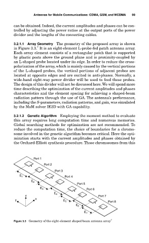
3.2.1.1 Array Geometry The geometry of the proposed array is shown
7
in Figure 3.3. It is an eight-element L-probe-fed patch antenna array.
Each array element consists of a rectangular patch that is supported
by plastic posts above the ground plane and is proximity-coupled by
an L-shaped probe located under its edge. In order to reduce the cross-
polarization of the array, which is mainly caused by the vertical portions
of the L-shaped probes, the vertical portions of adjacent probes are
located at opposite edges and are excited in anti-phases. Normally, a
wide-band eight-way power divider will be used to feed these probes.
The design of this divider will not be discussed here. We will spend more
time describing the optimization of the current amplitudes and phases
characteristics and the element spacing for achieving a shaped-beam
radiation pattern through the use of GA. The antenna’s performance,
including the S-parameters, radiation patterns, and gain, was simulated
by the MoM solver IE3D with GA capability.
3.2.1.2 Genetic Algorithm Employing the moment method to evaluate
this array requires long computation time and numerous memories.
Global searching methods for optimization are not recommended. To
reduce the computation time, the choice of boundaries for a chromo-
some involved in the genetic algorithm becomes critical. Here the opti-
mization starts with the current amplitudes and phases obtained by
the Orchard-Elliott synthesis procedure. Those chromosomes from this
Port 1
Port 2
Port 3
E 1 Port 4
E 2
Port 5
E 3 Port 6
E
z 4 Port 7
y x E 5 Port 8
E 6
E 7
Figure 3.3 Geometry of the eight-element shaped beam antenna array 7