
Page 134 - Antennas for Base Stations in Wireless Communications
P. 134
Antennas for Mobile Communications: CDMA, GSM, and WCDMA 107
The antenna has over a 90° horizontal beamwidth and low backlobe
radiations in both planes, which make it very suitable for use in sectors
with large angles.
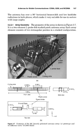
3.2.2.1 Array Geometry The geometry of the array is shown in Figure 3.7.
It is a two-element L-probe-fed stacked patch antenna array. Each array
element consists of two rectangular patches in a stacked configuration.
Elements spacing
= 0.84l X
Y 0
0.39l 0
Stacked
0.1l 0 patch
0.39l 0
0.137l 0
Lower
patch
L-probe feed
Din-connector Plastic screw Cutting slots
(a)
Cutting slots 0.038l 0 0.39l 0
0.119l 0 0.142l 0
1.69l 0 0.07l 0
Front view Side view
Plastic screw
Power divider
Ground Plane
0.137l 0
0.1l 0 0.623l 0
x
0.193
y
Top view
(b)
Figure 3.7 Geometry of the 90° linearly polarized antenna array: (a) prototype and
8
(b) different views (© 2005 IEEE)