
Page 162 - Antennas for Base Stations in Wireless Communications
P. 162
Advanced Antennas for Radio Base Stations 135
3 3
120º 2 120º 2
d d
1 1
φ = 0 φ 3 φ 2
1
1 3 2
Divider
1 3 2
(a)
(b)
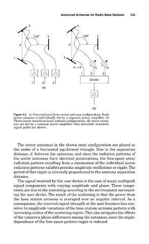
Figure 4.2 (a) Conventional three-sector antenna configuration. Each
sector antenna is individually fed by a separate power amplifier. (b)
Three-sector omnidirectional antenna configuration. All sector anten-
nas are fed by a common power amplifier. Only downlink (transmit)
signal paths are shown.
The sector antennas in the shown omni configuration are placed at
the nodes of a horizontal equilateral triangle. Due to the separation
distance, d, between the antennas, and since the radiation patterns of
the sector antennas have identical polarizations, the free-space array
radiation pattern resulting from a summation of the individual sector
radiation patterns exhibits periodic amplitude oscillations or ripple. The
period of this ripple is inversely proportional to the antenna separation
distance.
The signal received by the user device is the sum of many multipath
signal components with varying amplitude and phase. These compo-
nents are due to the scattering occurring in the environment surround-
ing the user device. The result of the scattering is that the power from
the base station antenna is averaged over an angular interval. As a
consequence, the received signal strength at the user becomes less sen-
sitive to amplitude variations of the base station antenna pattern with
increasing radius of the scattering region. This also mitigates the effects
of the unknown phase differences among the antennas, since the angle-
dependence of the free-space pattern ripple is reduced.