
Page 167 - Antennas for Base Stations in Wireless Communications
P. 167
140 Chapter Four
is pointed toward the cell border. This means that interference signals
toward neighboring cells are reduced at the cost of lower antenna gain for
14
devices located at or near the cell border. The reduction in gain at the cell
border due to downtilt is often not a problem for densely planned systems,
i.e., system with small inter-site distances where path loss is not a limit-
ing factor, since capacity (and, hence, interference) is the main concern. In
metropolitan environments with high antenna installations, beamtilting
far beyond 10° below the horizon is sometimes applied. Beamtilt has been
frequently used in large-scale Personal Digital Cellular (PDC) systems
since their introduction, and it is frequently used today in many mobile
communication cellular networks. 15
Two main methods for tilting an antenna beam exist, and they are
used either separately or in combination. The simplest method is to
mechanically tilt the antenna while the more sophisticated method
16
utilizes electrical beamtilt. Mechanical beamtilt affects the antenna
radiation differently along the horizontal plane. For example, if the
main beam in a three-sector system is tilted downward, then the back-
lobe is tilted upward while the wide angle sidelobes are almost unaf-
fected. Electrical beamtilt, on the other hand, has essentially the same
tilt effect on the radiation pattern for all azimuth angles for cylinder-
shaped antennas, such as conventional sector antennas, when these
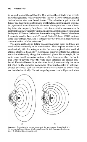
are installed vertically. Plots of iso-path gain curves in Figure 4.6 show
(a) (b)
Figure 4.6 Iso-path gain curves on ground for an antenna downtilted 10°:
(a) mechanical downtilt and (b) electrical downtilt. Main beam peak points at
the × (5 dB steps between contours).