
Page 170 - Antennas for Base Stations in Wireless Communications
P. 170
Advanced Antennas for Radio Base Stations 143
0
−5
−10
−15
−20
−25
−30
−35
−60 −40 −20 0 20 40 60
(a)
0
−5
−10
−15
−20
−25
−30
−35
−60 −40 −20 0 20 40 60
(b)
0
−5
−10
−15
−20
−25
−30
−35
−60 −40 −20 0 20 40 60
(c)
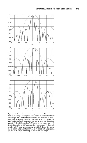
Figure 4.9 Elevation radiation pattern in dB as a func-
tion of the angle in degrees. The antenna consists of four
subarrays with four elements each. Black lines indicate
the total scanned radiation pattern and gray lines the
fixed subpanel radiation pattern. (a) 0° scan angle, subar-
ray at 0° fixed tilt angle; (b) 5° scan angle, subarray at 0°
fixed tilt angle; (c) 10° scan angle, subarray at 0° fixed tilt
angle; (d) 0° scan angle, subarray at 5.5° fixed tilt angle;
(e) 5° scan angle, subarray at 5.5° fixed tilt angle; and
(f) 10° scan angle, subarray at 5.5° fixed tilt angle.