
Page 171 - Antennas for Base Stations in Wireless Communications
P. 171
144 Chapter Four
0
−5
−10
−15
−20
−25
−30
−35
−60 −40 −20 0 20 40 60
(d)
0
−5
−10
−15
−20
−25
−30
−35
−60 −40 −20 0 20 40 60
(e)
0
−5
−10
−15
−20
−25
−30
−35
−60 −40 −20 0 20 40 60
(f)
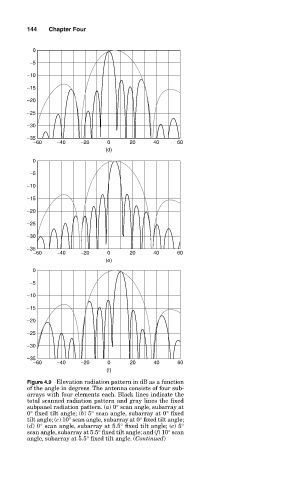
Figure 4.9 Elevation radiation pattern in dB as a function
of the angle in degrees. The antenna consists of four sub-
arrays with four elements each. Black lines indicate the
total scanned radiation pattern and gray lines the fixed
subpanel radiation pattern. (a) 0° scan angle, subarray at
0° fixed tilt angle; (b) 5° scan angle, subarray at 0° fixed
tilt angle; (c) 10° scan angle, subarray at 0° fixed tilt angle;
(d) 0° scan angle, subarray at 5.5° fixed tilt angle; (e) 5°
scan angle, subarray at 5.5° fixed tilt angle; and (f) 10° scan
angle, subarray at 5.5° fixed tilt angle. (Continued)