
Page 169 - Antennas for Base Stations in Wireless Communications
P. 169
142 Chapter Four
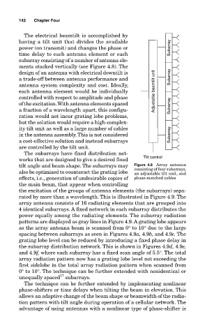
The electrical beamtilt is accomplished by
having a tilt unit that divides the available
power (on transmit) and changes the phase or Subarray
time delay to each antenna element or each
subarray consisting of a number of antenna ele-
ments stacked vertically (see Figure 4.8). The
design of an antenna with electrical downtilt is
a trade-off between antenna performance and Subarray
antenna system complexity and cost. Ideally,
each antenna element would be individually Adjustable beamtilt unit
controlled with respect to amplitude and phase
of the excitation. With antenna elements spaced Subarray
a fraction of a wavelength apart, this configu-
ration would not incur grating lobe problems,
but the solution would require a high-complex-
ity tilt unit as well as a large number of cables
in the antenna assembly. This is not considered Subarray
a cost-effective solution and instead subarrays
are controlled by the tilt unit.
The subarrays have fixed distribution net-
works that are designed to give a desired fixed Tilt control
tilt angle and beam shape. The subarrays may Figure 4.8 Array antenna
also be optimized to counteract the grating lobe consisting of four subarrays,
an adjustable tilt unit, and
effects, i.e., generation of undesirable copies of phase-matched cables
the main beam, that appear when controlling
the excitation of the groups of antenna elements (the subarrays) sepa-
rated by more than a wavelength. This is illustrated in Figure 4.9. The
array antenna consists of 16 radiating elements that are grouped into
4 identical subarrays. A fixed network in each subarray distributes the
power equally among the radiating elements. The subarray radiation
patterns are displayed as gray lines in Figure 4.9. A grating lobe appears
as the array antenna beam is scanned from 0° to 10° due to the large
spacing between subarrays as seen in Figures 4.9a, 4.9b, and 4.9c. The
grating lobe level can be reduced by introducing a fixed phase delay in
the subarray distribution network. This is shown in Figures 4.9d, 4.9e,
and 4.9f, where each subarray has a fixed scan angle of 5.5°. The total
array radiation pattern now has a grating lobe level not exceeding the
first sidelobe in the total array radiation pattern when scanned from
0° to 10°. The technique can be further extended with nonidentical or
17
unequally spaced subarrays.
The technique can be further extended by implementing nonlinear
phase-shifters or time delays when tilting the beam in elevation. This
allows an adaptive change of the beam shape or beamwidth of the radia-
tion pattern with tilt angle during operation of a cellular network. The
advantage of using antennas with a nonlinear type of phase-shifter is