
Page 173 - Antennas for Base Stations in Wireless Communications
P. 173
146 Chapter Four
sectorized systems as well as in multibeam antenna systems that are
mainly focused on exploiting the azimuth dimension.
4.7.1 Case Study
Antenna beamtilt is an efficient way of also improving system capac-
ity in re-use one systems, such as WCDMA, although there are funda-
mental differences in the interference situations between GSM and
WCDMA. In WCDMA downlink, for example, the desired user and a
user being interfered can be located fairly close to each other, such as
on either side of the cell border.
The setting of the beamtilt angle has been evaluated in a re-use one
14
three-sector network. All users are assumed to be uniformly distributed
in the network and all traffic assumed to be speech. Furthermore, there
are identical antennas in each cell and an identical electrical beamtilt
angle is applied to all base stations. Six different radiation patterns
are used in the study (see Table 4.1) and two types of network layouts,
one is the Ericsson cell plan and the other one is the Bell cell plan. The
65° azimuth half-power beamwidth (HPBW) pattern is evaluated in the
Ericsson cell plan (Figure 4.1e), whereas the 90° azimuth patterns are
evaluated in both the Bell cell plan (Figure 4.1c) and the Ericsson cell
plan (Figure 4.1f). A 120° HPBW pattern is evaluated in the Bell cell
plan only. The relative sidelobe level (SLL) is set to –15 dB in both the
elevation and the azimuth plane. The antenna installation height is 30 m
in all cases, and the site-to-site distance is 2000 m for high-gain (20 dBi)
antennas and 800 m when low-gain (17 dBi) antennas are analyzed.
The evaluated performance is the WCDMA pole capacity defined as
the maximum capacity possible while still fulfilling the desired qual-
ity for each user. This capacity is found by loading the system until no
solutions to the power equation can be found, i.e., the SINR quality
requirement is no longer fulfilled. At pole capacity, the required power
asymptotically approaches infinity.
Pole capacity, the maximal theoretical load, is shown in Figure 4.11 for
high- and low-gain antennas. One observation is that a proper beamtilt
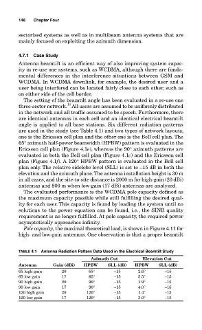
TABLE 4.1 Antenna Radiation Pattern Data Used in the Electrical Beamtilt Study
Azimuth Cut Elevation Cut
Antenna Gain (dBi) HPBW SLL (dB) HPBW SLL (dB)
65 high gain 20 65° –15 2.6° –15
65 low gain 17 65° –15 5.5° –15
90 high gain 20 90° –15 1.9° –15
90 low gain 17 90° –15 4.0° –15
120 high gain 20 120° –15 1.4° –15
120 low gain 17 120° –15 3.0° –15