
Page 163 - Antennas for Base Stations in Wireless Communications
P. 163
136 Chapter Four
The scattering behavior can be modeled by using power-averaged
radiation patterns. The averaging is performed by calculating the mean
value of the radiated power (uniformly weighted) over all angles within
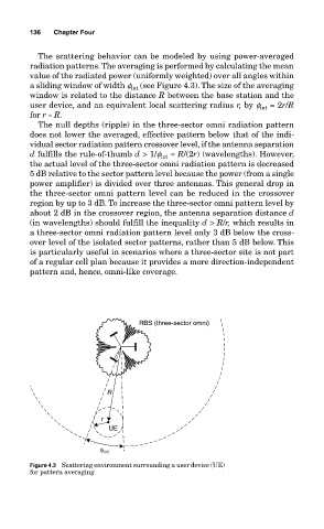
a sliding window of width f int (see Figure 4.3). The size of the averaging
window is related to the distance R between the base station and the
user device, and an equivalent local scattering radius r, by f int = 2r/R
for r « R.
The null depths (ripple) in the three-sector omni radiation pattern
does not lower the averaged, effective pattern below that of the indi-
vidual sector radiation pattern crossover level, if the antenna separation
d fulfills the rule-of-thumb d > 1/f int ≈ R/(2r) (wavelengths). However,
the actual level of the three-sector omni radiation pattern is decreased
5 dB relative to the sector pattern level because the power (from a single
power amplifier) is divided over three antennas. This general drop in
the three-sector omni pattern level can be reduced in the crossover
region by up to 3 dB. To increase the three-sector omni pattern level by
about 2 dB in the crossover region, the antenna separation distance d
(in wavelengths) should fulfill the inequality d > R/r, which results in
a three-sector omni radiation pattern level only 3 dB below the cross-
over level of the isolated sector patterns, rather than 5 dB below. This
is particularly useful in scenarios where a three-sector site is not part
of a regular cell plan because it provides a more direction-independent
pattern and, hence, omni-like coverage.
RBS (three-sector omni)
R
r
UE
φ int
Figure 4.3 Scattering environment surrounding a user device (UE)
for pattern averaging