
Page 181 - Antennas for Base Stations in Wireless Communications
P. 181
154 Chapter Four
average relative coverage improvement of about 5 dB for almost the
entire cell, corresponding to the full gain difference between the anten-
nas, thus verifying that the modular high-gain antenna retains its gain
characteristic in a real propagation environment. Assuming a radial cell
size of 15km, the trial shows a coverage improvement of about 5 dB in
more than 95% of the cell area.
4.9 Higher Order Sectorization
21
Higher order sectorization is conceptually straightforward to imple-
ment because there is no principal change in the base station structure
compared to the reference system. Moreover, the radio network algo-
rithms are unaffected, which means the interface between the base
station and the radio network controller (RNC) is unchanged. The trans-
mission capacity over the back-haul interface, however, needs to meet
the demands from increased traffic over the air interface offered by the
increased sectorization.
The changes in a system with higher order sectorization, compared
to the reference system, are basically that there are N > 3 independent
coverage areas, instead of three, with unique cell identities that are
serviced by the same radio base station (or site). The most common
configuration is based on dividing the azimuth angular interval sur-
rounding a site into fractions of 360°, typically 360°/N per sector in a
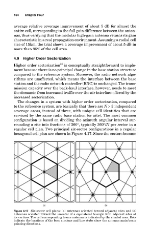
regular cell plan. Two principal six-sector configurations in a regular
hexagonal cell plan are shown in Figure 4.17. Since the sectors become
Figure 4.17 Six-sector cell plans: (a) antennas oriented toward adjacent sites and (b)
antennas oriented toward the incenter of a equilateral triangle with adjacent sites at
its vertices. The cell corresponding to one antenna is indicated by the shaded area. Dots
indicate the locations of the base stations and line stubs show the antenna main beam
pointing directions.