
Page 186 - Antennas for Base Stations in Wireless Communications
P. 186
Advanced Antennas for Radio Base Stations 159
beams at RF within the antenna unit. In such an implementation, the
number of beams generally equals the number of antenna elements or
columns. A Butler matrix can be thought of as a hardware realization
of the Fast Fourier Transform (FFT); hence, the beam orthogonality
is a consequence of the property that the inner product of the output
port excitations of the Butler matrix is a Kronecker delta-function δ mn ,
where m and n are indexes of the Butler matrix input port. When the
Butler matrix output ports are connected to equidistant antenna ele-
ments or, more commonly, columns of antenna elements in an array
antenna, the radiation pattern (array factor) beam peak corresponding
to a given input port coincides with pattern nulls for all other input
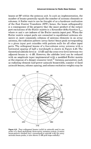
ports. The orthogonal beams of a four-column array antenna with a
horizontal spacing of half a wavelength is shown in Figure 4.20. The
theoretical sidelobe level is –13 dB and the cross-over level between two
adjacent beams is –4 dB. However, the sidelobe level can be reduced
with an amplitude taper implemented with a modified Butler matrix
28
at the expense of a deeper crossover level. Antenna parameters such
as radiating element half-power azimuth beamwidth, number of fixed
azimuth beams, column spacing, and column excitation weights may be
90
120 60
150 30
180 0
210 330
240 300
270
Figure 4.20 Four orthogonal beams (solid) in azimuth used in one
sector of a fixed multibeam three-sector antenna system. A sector
beam pattern (dashed line), normalized to coincide with the array
antenna beam peaks, is also shown (5 dB grid steps radially).