
Page 189 - Antennas for Base Stations in Wireless Communications
P. 189
162 Chapter Four
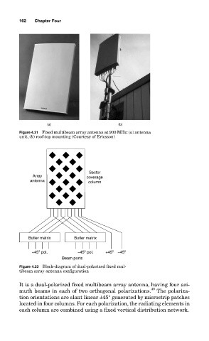
Figure 4.21 Fixed multibeam array antenna at 900 MHz: (a) antenna
unit, (b) roof-top mounting (Courtesy of Ericsson)
Sector
Array coverage
antenna column
Butler matrix Butler matrix
+45º pol. −45º pol. +45º −45º
Beam ports
Figure 4.22 Block-diagram of dual-polarized fixed mul-
tibeam array antenna configuration
It is a dual-polarized fixed multibeam array antenna, having four azi-
40
muth beams in each of two orthogonal polarizations. The polariza-
tion orientations are slant linear ±45° generated by microstrip patches
located in four columns. For each polarization, the radiating elements in
each column are combined using a fixed vertical distribution network.