
Page 185 - Antennas for Base Stations in Wireless Communications
P. 185
158 Chapter Four
Beamforming network
Dx
Dx
Dx
Dx
Rx Rx Rx Rx
D
O Switch
A
Equalization & combining Tx
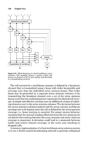
Figure 4.19 Block diagram of a fixed multibeam array
antenna. The example shows a system where the
beams are formed at RF in both uplink and downlink
in a beamforming network.
The cell serviced by a multibeam antenna is defined by a broadcast
channel that is transmitted using a beam with wider beamwidth and
coverage area than the individual array antenna beams. This wider
beam may be generated by a separate sector antenna (column) or by
transmitting the broadcast channel over a set of the array antenna
beams such that the combined pattern represents the desired cell cover-
age. A simple and effective solution uses an additional column of radiat-
ing elements next to the array antenna columns. The deviation between
the sector antenna radiation pattern and the array antenna multibeam
envelope has to be limited since the cell is defined by the sector pattern
coverage; i.e., beam tracking is essential. For proper system behavior,
ensuring that the mutual coupling effects between the two antennas do
not distort the tracking between the array antenna and sector antenna
coverage is important. A deviation could lead to a mismatch between
traffic and control channel coverage, in the worst case resulting in
dropped calls.
A common implementation of a fixed multibeam array antenna system
is to use a Butler matrix beamforming network to generate orthogonal