
Page 190 - Antennas for Base Stations in Wireless Communications
P. 190
Advanced Antennas for Radio Base Stations 163
A sparse element grid is implemented in order to minimize feed net-
work losses and coupling effects among radiating elements. On the other
hand, grating lobes are avoided to maintain beam pattern control at
all beam positions. The columns are spaced half a wavelength apart
with radiating elements positioned in a triangular grid. By using the
triangular grid, grating lobes come close to the visible space only for
the outermost beam positions, where achieved gain is not as critical as
for the center beams.
The horizontal beamforming networks used in the antenna are Butler
matrices with equal number of antenna ports and beam ports, with
one Butler matrix per polarization connected to the four array columns
of radiating elements, generating four beams with +45° polarization
and four beams with –45° polarization. Beam generation from the
Butler matrix results in low loss patterns but with a cross-over depth
of approximately –4 dB between adjacent beams, as stated previously.
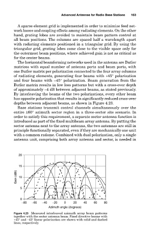
By interleaving the beams of the two polarizations, every other beam
has opposite polarization that results in significantly reduced cross-over
depths between adjacent beams, as shown in Figure 4.23.
Base stations transmit control channels simultaneously over the
entire ±60° azimuth sector region in a three-sector site scenario. In
order to satisfy this requirement, a separate sector antenna function is
introduced as part of the fixed multibeam array antenna. By putting the
sector antenna next to the array antenna, the two antennas are still in
principle functionally separated, even if they are mechanically one unit
with a common radome. Combined with dual polarization, only a single
antenna unit, comprising both array antenna and sector, is needed in
20
15
Gain (dBi) 10
5
0
−80 −60 −40 −20 0 20 40 60 80
Azimuth angle (degrees)
Figure 4.23 Measured interleaved azimuth array beam patterns
together with the sector antenna beam. Fixed directive beams with
+45° and –45° linear polarization are shown with solid and dashed
lines, respectively.