
Page 195 - Antennas for Base Stations in Wireless Communications
P. 195
168 Chapter Four
Dx
Dx
Dx
Dx
Beamforming network
Rx Rx Rx Rx Tx Tx Tx Tx
D
O Beam steer
A
Equalization & combining
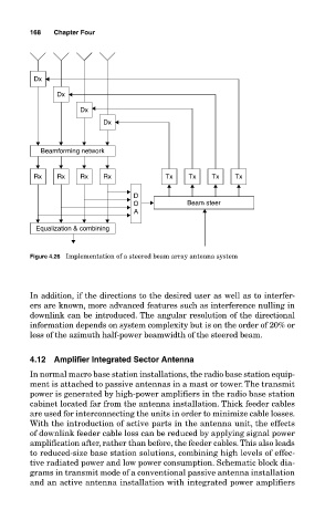
Figure 4.26 Implementation of a steered beam array antenna system
In addition, if the directions to the desired user as well as to interfer-
ers are known, more advanced features such as interference nulling in
downlink can be introduced. The angular resolution of the directional
information depends on system complexity but is on the order of 20% or
less of the azimuth half-power beamwidth of the steered beam.
4.12 Amplifier Integrated Sector Antenna
In normal macro base station installations, the radio base station equip-
ment is attached to passive antennas in a mast or tower. The transmit
power is generated by high-power amplifiers in the radio base station
cabinet located far from the antenna installation. Thick feeder cables
are used for interconnecting the units in order to minimize cable losses.
With the introduction of active parts in the antenna unit, the effects
of downlink feeder cable loss can be reduced by applying signal power
amplification after, rather than before, the feeder cables. This also leads
to reduced-size base station solutions, combining high levels of effec-
tive radiated power and low power consumption. Schematic block dia-
grams in transmit mode of a conventional passive antenna installation
and an active antenna installation with integrated power amplifiers