
Page 196 - Antennas for Base Stations in Wireless Communications
P. 196
Advanced Antennas for Radio Base Stations 169
Active antenna
Passive antenna
Low loss Small diameter
feeder cable feeder cable
High output Low output
power base power base
station station
(a) (b)
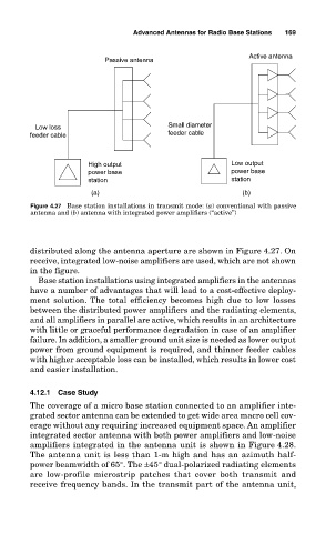
Figure 4.27 Base station installations in transmit mode: (a) conventional with passive
antenna and (b) antenna with integrated power amplifiers (“active”)
distributed along the antenna aperture are shown in Figure 4.27. On
receive, integrated low-noise amplifiers are used, which are not shown
in the figure.
Base station installations using integrated amplifiers in the antennas
have a number of advantages that will lead to a cost-effective deploy-
ment solution. The total efficiency becomes high due to low losses
between the distributed power amplifiers and the radiating elements,
and all amplifiers in parallel are active, which results in an architecture
with little or graceful performance degradation in case of an amplifier
failure. In addition, a smaller ground unit size is needed as lower output
power from ground equipment is required, and thinner feeder cables
with higher acceptable loss can be installed, which results in lower cost
and easier installation.
4.12.1 Case Study
The coverage of a micro base station connected to an amplifier inte-
grated sector antenna can be extended to get wide area macro cell cov-
erage without any requiring increased equipment space. An amplifier
integrated sector antenna with both power amplifiers and low-noise
amplifiers integrated in the antenna unit is shown in Figure 4.28.
The antenna unit is less than 1-m high and has an azimuth half-
power beamwidth of 65°. The ±45° dual-polarized radiating elements
are low-profile microstrip patches that cover both transmit and
receive frequency bands. In the transmit part of the antenna unit,