
Page 199 - Antennas for Base Stations in Wireless Communications
P. 199
172 Chapter Four
Multi- Sector
beam
array coverage
antenna column
Butler matrix Butler matrix
Dx Dx
+45° pol. Dx Dx −45° pol. Dx Dx Dx Dx
Dx Dx
Hybrid matrix Hybrid matrix
Hybrid matrix Hybrid matrix
+45° pol. −45° pol. +45° −45°
Beam ports
(b)
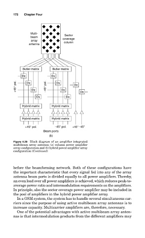
Figure 4.29 Block diagram of an amplifier integrated
multibeam array antenna: (a) column power amplifier
array configuration and (b) hybrid power amplifier array
configuration (Continued)
before the beamforming network. Both of these configurations have
the important characteristic that every signal fed into any of the array
antenna beam ports is divided equally to all power amplifiers. Thereby,
an even load over all power amplifiers is achieved, which reduces peak-to-
average power ratio and intermodulation requirements on the amplifiers.
In principle, also the sector coverage power amplifier may be included in
the pool of amplifiers in the hybrid power amplifier array.
In a GSM system, the system has to handle several simultaneous car-
riers since the purpose of using active multibeam array antennas is to
increase capacity. Multicarrier amplifiers are, therefore, necessary.
One of the potential advantages with active multibeam array anten-
nas is that intermodulation products from the different amplifiers may