
Page 226 - Antennas for Base Stations in Wireless Communications
P. 226
Antenna Issues and Technologies for Enhancing System Capacity 199
−60
−70
Mutual coupring [dB] −80
−90
−100
−110 4λ
2.1 2.12 2.14 2.16 2.18 2.2
Frequency [GHz]
Figure 5.25 Mutual coupling characteristics of booster antennas
antenna—for instance, a cosecant beam pattern—is preferable because
the shaped-beam pattern in a service area is capable of providing a
sufficiently constant received power level for mobile users and uniform
receiving power levels in spite of the cell edge while imparting only a
23
slight interference power level to other adjacent cells. The cosecant
beam pattern can be achieved when the elements of the array are fed
with linearly varied amplitudes and phases.
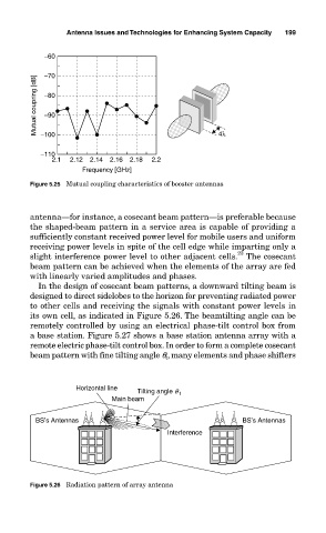
In the design of cosecant beam patterns, a downward tilting beam is
designed to direct sidelobes to the horizon for preventing radiated power
to other cells and receiving the signals with constant power levels in
its own cell, as indicated in Figure 5.26. The beamtilting angle can be
remotely controlled by using an electrical phase-tilt control box from
a base station. Figure 5.27 shows a base station antenna array with a
remote electric phase-tilt control box. In order to form a complete cosecant
beam pattern with fine tilting angle q t , many elements and phase shifters
Horizontal line Tilting angle q t
Main beam
BS’s Antennas BS’s Antennas
Interference
Figure 5.26 Radiation pattern of array antenna