
Page 227 - Antennas for Base Stations in Wireless Communications
P. 227
200 Chapter Five
Microstrip line
Beamtilting angle
Phase q t
shifter #4 #2
Printed
antenna
#3 #1
Electrical phase-tilt Phase
control box
(a) An antenna with a tilt control box (b) A printed antenna
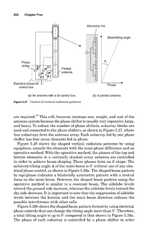
Figure 5.27 Control of vertical radiation patterns
24
are required. This will, however, increase size, weight, and cost of the
antenna system because the phase shifter is usually very expensive, large,
and heavy. To reduce the number of phase shifters, subarray blocks are
used and connected to the phase shifters, as shown in Figure 5.27, where
four subarrays form the antenna array. Each subarray fed by one phase
shifter has four array elements fed in-phase.
Figure 5.28 shows the shaped vertical radiation patterns by using
equiphase, namely the elements with the same phase difference and an
operative method. With the operative method, the phases of the top and
bottom elements in a vertically stacked array antenna are controlled
in order to achieve beam-shaping. These phases form an S shape. The
achieved tilting angle q t of the main beam is 5° without use of any elec-
trical phase control, as shown in Figure 5.28a. The shaped beam pattern
by equiphase indicates a bilaterally symmetric pattern with a central
focus on the main beam. However, the shaped beam pattern using the
operative method is similar to a cosecant beam. The sidelobe levels
toward the ground side increase, whereas the sidelobe levels toward the
sky side decrease. It is important to note that the suppression of sidelobe
levels between the horizon and the main beam direction reduces the
possible interference with other cells.
Figure 5.28b shows the shaped beam pattern formed by using electrical
phase controls that can change the tilting angle more than 3°. Therefore,
a total tilting angle is up to 8° compared to that shown in Figure 5.28a.
The phase of each subarray is controlled by a phase shifter in order