
Page 222 - Antennas for Base Stations in Wireless Communications
P. 222
Antenna Issues and Technologies for Enhancing System Capacity 195
0
−10
[dB] −20
E-plane
−30
−40
H-plane
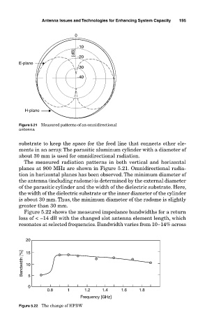
Figure 5.21 Measured patterns of an omnidirectional
antenna
substrate to keep the space for the feed line that connects other ele-
ments in an array. The parasitic aluminum cylinder with a diameter of
about 30 mm is used for omnidirectional radiation.
The measured radiation patterns in both vertical and horizontal
planes at 900 MHz are shown in Figure 5.21. Omnidirectional radia-
tion in horizontal planes has been observed. The minimum diameter of
the antenna (including radome) is determined by the external diameter
of the parasitic cylinder and the width of the dielectric substrate. Here,
the width of the dielectric substrate or the inner diameter of the cylinder
is about 30 mm. Thus, the minimum diameter of the radome is slightly
greater than 30 mm.
Figure 5.22 shows the measured impedance bandwidths for a return
loss of < −14 dB with the changed slot antenna element length, which
resonates at selected frequencies. Bandwidth varies from 10−14% across
20
Bandwidth [%] 15
10
0 5
0.8 1 1.2 1.4 1.6 1.8
Frequency [GHz]
Figure 5.22 The change of HPBW