
Page 218 - Antennas for Base Stations in Wireless Communications
P. 218
Antenna Issues and Technologies for Enhancing System Capacity 191
φ = 0° 0.8-GHz
330° 30° 1.5-GHz
2-GHz
−10
300° [dB] 60°
−20
−30
270° 90°
240° 120°
210° 150°
180°
(a) Measured patterns without parasitic conductors
0.8-GHz
φ = 0° 1.5-GHz
330° 30° 2-GHz
−10
300° [dB] 60°
−20
−30
270° 90°
240° 120°
210° 150°
180°
(b) Measured patterns with parasitic conductors
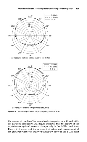
Figure 5.16 Measured patterns of triple frequency-band antenna
the measured results of horizontal radiation patterns with and with-
out parasitic conductors. This figure indicates that the HPBW of the
triple frequency-band antenna changes only in the 2-GHz band. Also,
Figure 5.16 shows that the optimized structure and arrangement of
the parasitic conductors achieved the HPBW of 90° in the 2-GHz band