
Page 213 - Antennas for Base Stations in Wireless Communications
P. 213
186 Chapter Five
in Figure 5.6c, although the radiation performance of the antenna
remains the same as the antenna with a flat reflector, as depicted in
Figure 5.6a. From this, we can conclude that the diameter of the antenna
can be narrowed by optimizing the reflector’s shape while also maintain-
ing radiation performance.
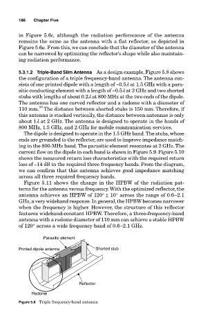
5.3.1.2 Triple-Band Slim Antenna As a design example, Figure 5.8 shows
the configuration of a triple frequency-band antenna. The antenna con-
sists of one printed dipole with a length of ~0.5l at 1.5 GHz with a para-
sitic conducting element with a length of ~0.5l at 2 GHz and two shorted
stubs with lengths of about 0.2l at 800 MHz at the two ends of the dipole.
The antenna has one curved reflector and a radome with a diameter of
10
110 mm. The distance between shorted stubs is 150 mm. Therefore, if
this antenna is stacked vertically, the distance between antennas is only
about 1l at 2 GHz. The antenna is designed to operate in the bands of
800 MHz, 1.5 GHz, and 2 GHz for mobile communication services.
The dipole is designed to operate in the 1.5 GHz band. The stubs, whose
ends are grounded to the reflector, are used to improve impedance match-
ing in the 800-MHz band. The parasitic element resonates at 2 GHz. The
current flow on the dipole in each band is shown in Figure 5.9. Figure 5.10
shows the measured return loss characteristics with the required return
loss of –14 dB in the required three frequency bands. From the diagram,
we can confirm that this antenna achieves good impedance matching
across all three required frequency bands.
Figure 5.11 shows the change in the HPBW of the radiation pat-
terns for the antenna versus frequency. With the optimized reflector, the
antenna achieves an HPBW of 120° ± 10° across the range of 0.6−2.1
GHz, a very wideband response. In general, the HPBW becomes narrower
when the frequency is higher. However, the structure of this reflector
features wideband-constant HPBW. Therefore, a three-frequency-band
antenna with a radome diameter of 110 mm can achieve a stable HPBW
of 120° across a wide frequency band of 0.6−2.1 GHz.
Parasitic element
Printed dipole antenna Shorted stub
Reflector
Radome
Figure 5.8 Triple frequency-band antenna