
Page 215 - Antennas for Base Stations in Wireless Communications
P. 215
188 Chapter Five
5.3.2 Narrow HPBW Antenna with
Parasitic Metal Conductors
In addition to stabilizing the HPBW response across a wideband/mul-
tiple bands, controlling the HPBW in the operating bands to cover the
desired sector area is also important. To accomplish this, antennas with
controlled HPBW have been designed.
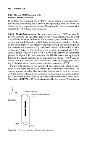
5.3.2.1 Single-Beam Antenna In order to narrow the HPBW, we usually
have to increase the size of the reflector in certain dimensions. To avoid
a significant increase in the size of the antenna, two slender metal con-
ductors are used. Consider a 0.5l dipole with a semi-cylinder reflector
as shown in Figure 5.12. Metal conductors having the same length as
the reflector are symmetrically positioned in front of the reflector with
a distance S between the dipole and the slender metal conductors. The
slender metal conductors are used to narrow the HPBW in horizontal
planes. In Figure 5.13, the change in the HPBW versus the spacing S
between the dipole and the metal conductors is shown. HPBW can be
varied from 110° (without metal conductors) to 60° by changing the spac-
ing S. Slender metal conductors can achieve narrower HPBW.
Figure 5.14 compares the measured and simulated radiation pat-
terns for the antennas with and without parasitic metal conductors. The
comparison reveals that the simulated results are in good agreement
with the measured results. An antenna with parasitic metal conductors
has a narrower HPBW than an antenna without the metal conductors.
The achieved HPBW is 90°, which is required by the system. The antenna
z
l/2 Dipole Antenna
x
y Semi-Cylinder Reflector
Conductor
~
D
S
Figure 5.12 120° beam antenna with parasitic conductors