
Page 219 - Antennas for Base Stations in Wireless Communications
P. 219
192 Chapter Five
TABLE 5.1 Measured HPBW
HPBW 800-MHz band 1.5-GHz band 2-GHz band
Without conductors 113.9° 112.5° 113.4°
With conductors 123.9° 129.8° 83.6°
without influencing the HPBW performance in the 800-MHz and 1.5-
GHz bands. Table 5.1 shows the change in HPBW in 800-MHz, 1.5-GHz,
and 2-GHz bands. Therefore, if the parameters of the metal conductors
are selected correctly, only the HPBW in the highest frequency band
can be changed as desired. The overall surface width of the antenna is
118 mm; the antenna aperture is 110 mm; and the metal conductors
are 4 mm. The overall size of this antenna is slightly larger than the
antenna without the conductors.
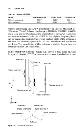
5.3.2.3 Dual-Beam Antenna Figure 5.17 shows a dual-beam antenna
for spatial diversity. 16,17 The two antennas were installed on a bent
Antenna #2
Reflector
Antenna #1
Dipole antenna #4
∼
z
∼
x ∼ ∼
Dipole antenna #1
y
Dipole antenna #3
Dipole antenna #2
y
z x
Antenna #1 Antenna #2
Dipole antenna #2 Dipole antenna #3
Dipole antenna #4
Dipole antenna #1
Reflector
Figure 5.17 Dual-beam antenna