
Page 247 - Antennas for Base Stations in Wireless Communications
P. 247
220 Chapter Six
because the interference between different cells operating at the same
frequency can be reduced substantially. Due to their wideband charac-
teristics and desirable radiation patterns, they can easily find conceiv-
able applications for the current wireless communication systems like
GSM1800/1900, 3G, WiFi, WiMax, ZigBee, and so on.
6.3.1 Basic Principle
To provide more detailed understanding of a complementary antenna
consisting of an electric dipole and a magnetic dipole for achieving a
unidirectional symmetric radiation pattern, this section begins with a
review of the characteristics of several previous works available in the
literature. The approach of exciting an electric dipole and a magnetic
dipole simultaneously for achieving an identical E- and H-plane radia-
35
tion pattern was first revealed by Clavin in 1954. Figure 6.13 shows
his proposed idea about two sources that have complementary types of
radiation characteristics oriented at right angles to one another. These
two sources can be realized by using an electric dipole and the open end
35
of a waveguide, which is mentioned in Clavin. Figure 6.13 describes
schematically how the field patterns of two complementary sources
would appear. An electric dipole and a magnetic dipole are separated by
a specific distance, which can be used to control the proper amplitude
and phase of two complementary sources so they can perform with equal
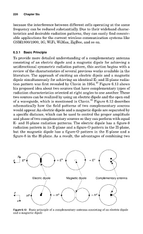
E- and H-plane radiation patterns. The electric dipole has a figure-8
radiation pattern in its E-plane and a figure-O pattern in the H-plane,
but the magnetic dipole has a figure-O pattern in the E-plane and a
figure-8 in the H-plane. As a result, the advantages of combining two
y
z E e + E h = E c
Electric dipole Magnetic dipole Complementary antenna
z h c
H e + H = H
x
Figure 6.13 Basic principle of a complementary antenna consisting of an electric dipole
and a magnetic dipole