Page 243 - Antennas for Base Stations in Wireless Communications
P. 243

216     Chapter Six

                                                       Parallel
                                                       stripline
                                                 Port 1


                                                                 Dielectric
                                       l 0 /4                    substrate
                   Microstrip
                     line
                     +
                    Port 2                                 Microstrip
                                                             line
                                 Resistor                     −
                                                            Port 3
                                                      Ground
                                                      plane

                  Figure 6.8  Geometry of the wideband 180° out-of-phase power divider 51

                      4

                     3.5
                                   Measured SWR
                                   Simulated SWR
                      3
                    SWR  2.5
                                          74%
                      2

                     1.5

                      1
                       1       1.5      2       2.5       3      3.5
                                       Frequency (GHz)
                                                                     50
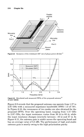
                  Figure 6.9  Simulated and measured SWRs of the proposed antenna
                  (© 2007 IEEE)
                  Figure 6.9 reveals that the proposed antenna can operate from 1.37 to
                  2.97 GHz with a measured impedance bandwidth (SWR ≤ 2) of 74%.
                  In Figure 6.10, the resonances of two modes are also obtained for the
                  proposed  DFPA.  Over  the  operating  band,  ranging  from  1.37  GHz
                  to 2.97 GHz, the input resistance varies from 30  Ω to 63 Ω, while
                  the input reactance changes interiorly between –10 Ω and 27 Ω. In
                  Figure 6.11, the antenna gain is stable across the operating band and
                  has an average value of 8.5 dBi. The performance of high and stable
                  antenna gain is mostly owing to the high polarization purity.
   238   239   240   241   242   243   244   245   246   247   248