
Page 239 - Antennas for Base Stations in Wireless Communications
P. 239
212 Chapter Six
2.5 10
Measured Simulated
2 8
SWR Gain (dBi)
1.5 6
1 4
1.5 1.6 1.7 1.8 1.9 2 2.1 2.2 2.3 2.4 2.5
Frequency (GHz)
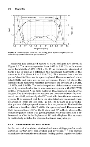
Figure 6.5 Measured and simulated SWRs and gains against frequency of the
meandering-probe fed stacked patch antenna 33
Measured and simulated results of SWR and gain are shown in
Figure 6.5. The antenna operates from 1.575 to 2.36 GHz with a mea-
sured bandwidth of 40% (SWR < 2). If the commercial standard of
SWR < 1.5 is used as a reference, the impedance bandwidth of the
antenna is 37% (from 1.6 to 2.325 GHz). The antenna has a stable
gain of about 9 dBi across its operating band. The measured and simu-
lated SWRs and gains are in good agreement. Figure 6.6 shows the
simulated and measured radiation patterns of the antenna at 1.6 GHz,
1.9 GHz, and 2.3 GHz. The radiation pattern of the antenna was mea-
sured by a near-field antenna measurement system with ORBIT/FR
MiDAS Cylindrical Near-Field Antenna Measurement and Analysis
System. The far-field radiation patterns are transformed from the mea-
sured near-field patterns by the FFT available from the measurement
system. It is observed that both the simulated and measured cross-
polarization levels are less than –20 dB. The E-plane co-polar radia-
tion pattern of the proposed antenna is also symmetric. The backlobe
radiation is less than –20 dB within the operating band. The measured
3-dB beamwidths are 66º in the E-plane and 76º in the H-plane at the
center frequency, which is in good agreement with the simulated 3-dB
beamwidths of 64º in the E-plane and 78º in the H-plane. This antenna
is particularly suitable for wideband antenna array design.
6.2.3 Differential-Plate Fed Patch Antenna
In the interest of realizing wideband antennas, differential-fed patch
antennas (DFPA) have been studied and developed. 48–49 The mutual
capacitance between the two adjacent feeding probes, together with the