
Page 237 - Antennas for Base Stations in Wireless Communications
P. 237
210 Chapter Six
0 dB 0 dB
−10 −10
−45 45 −45 45
−20 −20
−90 90 −90 90
5.0 GHz
−135 135 −135 135
180 180
(a) Single L-probe (b) Twin L-probe
Co-pol.
H-plane (x-z plane) E-plane (y-z plane)
Cross-pol.
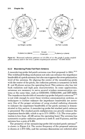
Figure 6.3 Measured radiation patterns at 5.0 GHz of (a) the single L-probe coupled
29
patch antenna and (b) the twin L-probe coupled patch antenna (© 2005 IEEE)
6.2.2 Meandering-Probe Fed Patch Antenna
A meandering-probe fed patch antenna was first proposed in 2004. 30,31
This wideband feeding mechanism not only can enhance the impedance
bandwidth of a patch antenna, but also can suppress the cross-polarization
level of the antenna. By aligning the center of the meandering probe
with the center of the patch, the radiation pattern is symmetric in both
E- and H-planes across the operating band. This antenna also has low
back radiation and high gain characteristics. In some applications,
antennas are necessary to serve several wireless communication sys-
tems at the same time, such as GSM1800, CDMA1900, and IMT-2000.
The impedance bandwidth of meandering-probe fed patch antennas 32–34
is not wide enough to cover these wireless communication systems, so
techniques to further enhance the impedance bandwidth are neces-
sary. One of the proper solutions of using stacked radiating elements
to enhance the impedance bandwidth of the patch antenna is demon-
strated in this section. A meandering-probe fed stacked patch antenna
is presented. The stacked patch configuration can greatly enhance the
impedance bandwidth, which is up to 37% (SWR < 1.5). The cross-polar-
ization is less than –20 dB across the operating band. The antenna has
symmetric co-polar radiation patterns in both E- and H-planes, and the
antenna has a gain of 9 dBi.
33
The geometry of the meandering-probe fed stacked patch antenna
is shown in Figure 6.4. The center frequency of the proposed antenna
is chosen at 1.975 GHz, and the antenna dimensions are selected after