
Page 235 - Antennas for Base Stations in Wireless Communications
P. 235
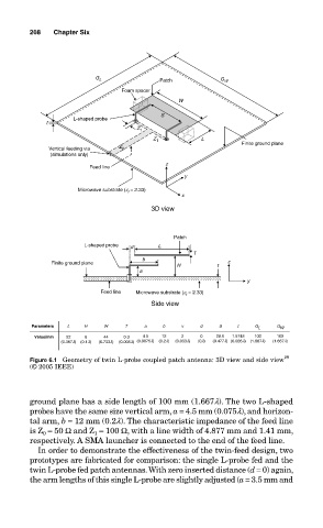
208     Chapter Six


                                   G L            Patch          G W
                                         Foam spacer
                                                       W
                                                   S
                             L-shaped probe
                      t
                                             Z 1
                                                 Z 1         L         Finite ground plane
                       Vertical feeding via  Z 0
                       (simulations only)
                                                    z
                                 Feed line
                                                        y
                              Microwave substrate (e r  = 2.33)
                                                        x
                                                3D view


                                                      Patch
                                L-shaped probe  d  L
                                                           T
                                              b
                        Finite ground plane            H         t  z
                                             a
                                                                        y
                                    Feed line  Microwave substrate (e  = 2.33)
                                                         r
                                                Side view


                   Parameters  L  H  W    T    a   b    v   d    S    t   G L  G W
                    Value/mm  22  6  44  0.3  4.5  12   2   0   28.6  1.5748  100  100
                          (0.367l)  (0.1l)  (0.733l)  (0.005l) (0.0075l)  (0.2l)  (0.033l)  (0l)  (0.477l) (0.026l)  (1.667l)  (1.667l)
                                                                                 29
                  Figure 6.1  Geometry of twin L-probe coupled patch antenna: 3D view and side view
                  (© 2005 IEEE)


                  ground plane has a side length of 100 mm (1.667l). The two L-shaped
                  probes have the same size vertical arm, a = 4.5 mm (0.075l), and horizon-
                  tal arm, b = 12 mm (0.2l). The characteristic impedance of the feed line
                  is Z 0  = 50 Ω and Z 1  = 100 Ω, with a line width of 4.877 mm and 1.41 mm,
                  respectively. A SMA launcher is connected to the end of the feed line.
                    In order to demonstrate the effectiveness of the twin-feed design, two
                  prototypes are fabricated for comparison: the single L-probe fed and the
                  twin L-probe fed patch antennas. With zero inserted distance (d = 0) again,
                  the arm lengths of this single L-probe are slightly adjusted (a = 3.5 mm and