
Page 238 - Antennas for Base Stations in Wireless Communications
P. 238
New Unidirectional Antennas for Various Wireless Base Stations 211
L 1
L 2
Upper patch
L 2
L 1
Bottom patch
w s
3D view
Ground plane Meandering probe
H 2
g h s
s h g H 1
SMA
connector
Side view
Parameters L 1 L 2 H 1 H 2 s h g w s
61 49 15.5 10.5 21 8.75 1.5 10
Value/mm
)
(0.4l ) (0.32l ) (0.1l ) (0.066l )(0.138l 0 (0.058l 0 (0.01l 0 ) (0.066l )
)
0
0
0
0
0
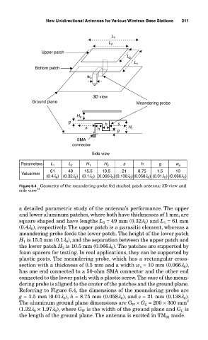
Figure 6.4 Geometry of the meandering-probe fed stacked patch antenna: 3D view and
side view 33
a detailed parametric study of the antenna’s performance. The upper
and lower aluminum patches, where both have thicknesses of 1 mm, are
square shaped and have lengths L = 49 mm (0.32l ) and L = 61 mm
0
2
1
(0.4l ), respectively. The upper patch is a parasitic element, whereas a
0
meandering probe feeds the lower patch. The height of the lower patch
H is 15.5 mm (0.1l ), and the separation between the upper patch and
1
0
the lower patch H is 10.5 mm (0.066l ). The patches are supported by
0
2
foam spacers for testing. In real applications, they can be supported by
plastic posts. The meandering probe, which has a rectangular cross-
section with a thickness of 0.5 mm and a width w = 10 mm (0.066l ),
s
0
has one end connected to a 50-ohm SMA connector and the other end
connected to the lower patch with a plastic screw. The case of the mean-
dering probe is aligned to the center of the patches and the ground plane.
Referring to Figure 6.4, the dimensions of the meandering probe are
g = 1.5 mm (0.01l ), h = 8.75 mm (0.058l ), and s = 21 mm (0.138l ).
0
0
0
The aluminum ground plane dimensions are G × G = 200 × 300 mm 2
L
W
(1.32l × 1.97l ), where G is the width of the ground plane and G is
L
W
0
0
the length of the ground plane. The antenna is excited in TM mode.
01