
Page 236 - Antennas for Base Stations in Wireless Communications
P. 236
New Unidirectional Antennas for Various Wireless Base Stations 209
b = 8 mm) for achieving the best impedance matching. The performances
of the two prototypes are measured by an HP8510-C Network Analyzer, a
compact range with ORBIT/FR MiDAS Far-Field Antenna Measurement
and Analysis System. As for the gain measurement, a NARDA-643 stan-
dard gain horn is used.
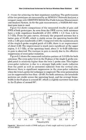
Figure 6.2 shows comparisons of the measured results of gain and
SWR of both prototypes. As seen from the SWR curves, both antennas
have a wide impedance bandwidth of 25% (SWR ≤ 1.5) from 4.42 to
5.7 GHz. From the gain curves, obviously the proposed antenna has a
better gain of 10 dBi, which is stable across the operating bandwidth
with a 1-dB-gain bandwidth of 26%. Compared with the maximum gain
of the single-L-probe coupled patch of 8 dBi, there is an improvement
of about 2 dB. The improvement is much more significant at the upper
region, 5–5.7 GHz, of the operating band, about 3- to 6-dB difference
in gain is observed. The increase in gain is mainly due to the effective
suppression of cross-polar radiation.
Figure 6.3 shows the measured radiation pattern at 5.0 GHz for both
antennas. The cross-polar level in the H-plane of the single L-probe cou-
pled patch is relatively higher than the twin L-probe case. This higher
cross-polar radiation is due to a stronger high-order mode radiation
from the patch as well as unwanted radiation from the vertical arm.
However, there is significant suppression in the cross-polar radiation
when the twin L-probe fed technique is employed. The cross-polarization
can be suppressed to less than –20 dB. For both antennas, the broadside
patterns are stable across the operating band, and the average beam-
width in the H-plane is around 56°, which is slightly narrower than that
in the E-plane of around 60°.
11
3.5 10
Gain 9
3 8
Twin-L-probe 7
SWR 2.5 Single-L-probe 6 5 Gain/dBi
2 4
3
1.5 2
SWR 1
1 0
4 4.2 4.4 4.6 4.8 5 5.2 5.4 5.6 5.8 6
Frequency/GHz
29
Figure 6.2 Measured results of SWR and gain of both single and twin L-probe cases
(© 2005 IEEE)