
Page 250 - Antennas for Base Stations in Wireless Communications
P. 250
New Unidirectional Antennas for Various Wireless Base Stations 223
M
M
J J
+
(a) Conventional (b) Quarter-wave patch (c) An antenna consisting of
half-wavelength antenna an electric dipole and
electric dipole antenna a quarter-wave patch
Figure 6.16 Principle of a wideband complementary antenna element for unidirectional
radiation 41
patch antenna has been selected as the magnetic dipole depicted in
Figure 6.16b. To combine these two antennas, the short-circuited patch
is placed vertically and is connected to the planar dipole, as illustrated
in Figure 6.16c. Based on this approach, a new wideband antenna has
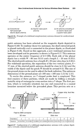
been developed and its geometry is shown in Figure 6.17. This antenna
operates at the center frequency of 2.5 GHz. Each side of the planar
dipole has a width W = 60 mm (0.5l) and a length L = 30 mm (0.25l).
The shorted patch antenna has a length H = 30 mm (also close to 0.25l).
For wideband operation, the separation of the two vertical plates, S =
17 mm, of the shorted patch antenna should be close to 0.14l and the
width of the dipole and the patch W should be around 0.5l. The size of
the ground plane can be used to adjust the back radiation. The optimum
dimensions of the ground plane are 160 mm × 160 mm (1.3l by 1.3l).
To excite the antenna, an Γ-shaped probe feed is employed. This
feed consists of three portions, which are made by folding a straight
metallic strip of rectangular cross-section into a Γ-shape. The first por-
tion, which is vertically oriented, has one end connected to a coaxial
launcher mounted below the grounded plane. This portion acts as a
S L c Copper strip, feed line
a
d W z
Copper plate
b
z H Air, e x
y 0
Ground plane
x
Feed to SMA connector SMA connector
3D view Side view
Parameters a b c d H L S W
Value/mm 9.5 (0.079l) 22 (0.183l) 1 (0.008l) 4.91 (0.040l) 30 (0.25l) 30 (0.25l) 17 (0.141l) 60 (0.5l)
Figure 6.17 Configuration of a wideband complementary antenna with a planar dipole
and a vertically oriented shorted patch 41