
Page 255 - Antennas for Base Stations in Wireless Communications
P. 255
228 Chapter Six
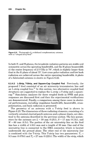
Figure 6.22 Photograph of a wideband complementary antenna
with a Γ-shaped strip feed 41
In both E- and H-planes, the broadside radiation patterns are stable and
symmetric across the operating bandwidth, and the H-plane beamwidth
at the center frequency of 2.5 GHz is 79°, which is slightly larger than
that in the E-plane of about 75°. Low cross-polar radiation and low back
radiation are achieved across the entire operating bandwidth. A photo
of a fabricated antenna is shown in Figure 6.22.
6.3.4.2 L-Strip, T-Strip, and Square-Cap Coupled Fed Previously, the
proposed Γ-feed consisted of an air microstrip transmission line and
54
an L-strip coupled line. In this section, two alternative coupled feed
structures are suggested to replace the L-strip: a T-strip and a square-
55
cap. Simulation analyses for these coupled feeds in SWR and gain
responses are discussed first and then the experimental verifications
are demonstrated. Finally, a comparison among these cases in electri-
cal performances, including impedance bandwidth, beamwidth, cross-
polarization, and back radiation is presented.
The geometry of an antenna with a T-strip feed is shown in
Figure 6.23. The dimensions of these radiating elements, consisting of a
vertically oriented shorted patch antenna and a planar dipole, are iden-
tical to the antenna described in the previous section. The key param-
eters for the antenna are L = 30 mm (0.25l), S = 17 mm (0.14l), and
W = 60 mm (0.5l). The portion of the air microstrip line on the feed
line has a width of 4.911 mm and a length of 30 mm. One end of the
microstrip line is connected to the SMA connector, which is located
underneath the ground plane. The other end of the microstrip line
is combined with the T-strip. This T-strip has two parameters: T =
1
9.5 mm (0.079l) and T = 27 mm (0.225l). The width of the strip, which
2