
Page 257 - Antennas for Base Stations in Wireless Communications
P. 257
230 Chapter Six
G L
S L
Copper plate d W
G W
Ground plane
z
y
Feed to SMA connector
x
Perspective view
10 mm
12.5 mm
24 mm
Square-cap
1 mm
Copper plate
H Air, e 0 z
x
Ground plane
SMA connector
Side view
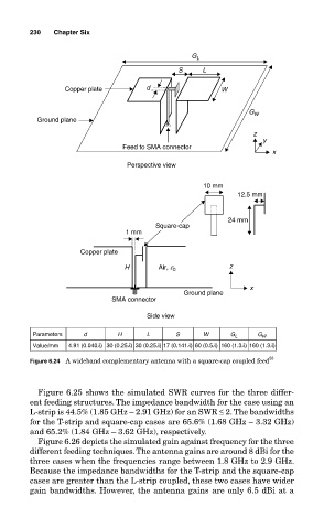
Parameters d H L S W G L G W
Value/mm 4.91 (0.040l) 30 (0.25l) 30 (0.25l) 17 (0.141l) 60 (0.5l) 160 (1.3l) 160 (1.3l)
Figure 6.24 A wideband complementary antenna with a square-cap coupled feed 55
Figure 6.25 shows the simulated SWR curves for the three differ-
ent feeding structures. The impedance bandwidth for the case using an
L-strip is 44.5% (1.85 GHz – 2.91 GHz) for an SWR ≤ 2. The bandwidths
for the T-strip and square-cap cases are 65.6% (1.68 GHz – 3.32 GHz)
and 65.2% (1.84 GHz – 3.62 GHz), respectively.
Figure 6.26 depicts the simulated gain against frequency for the three
different feeding techniques. The antenna gains are around 8 dBi for the
three cases when the frequencies range between 1.8 GHz to 2.9 GHz.
Because the impedance bandwidths for the T-strip and the square-cap
cases are greater than the L-strip coupled, these two cases have wider
gain bandwidths. However, the antenna gains are only 6.5 dBi at a