
Page 29 - Antennas for Base Stations in Wireless Communications
P. 29
2 Chapter One
polarization, input impedance, radiation patterns, gain, and efficiency.
An antenna in the transmitting mode has a maximum power acceptance.
An antenna in the receiving mode differs in its noise rejection proper-
ties. The designer should evaluate and measure all of these parameters
using various means.
1.1.1 Input Impedance
and Equivalent Circuits
As electromagnetic waves travel through the different parts of the
antenna system, from the source (device) to the feed line to the antenna
and finally to free space, they may encounter differences in impedance
at each interface. Depending on the impedance match, some fraction
of the wave’s energy will reflect back to the source, forming a standing
wave in the feed line. The ratio of maximum power to minimum power in
the wave can be measured and is called the standing wave ratio (SWR).
An SWR of 1:1 is ideal. An SWR of 1.5:1 is considered to be marginally
acceptable in low-power applications where power loss is more critical,
although an SWR as high as 6:1 may still be usable with the right equip-
ment. Minimizing impedance differences at each interface will reduce
SWR and maximize power transfer through each part of the system.
The frequency response of an antenna at its port is defined as input
impedance (Z in ). The input impedance is the ratio between the volt-
age and currents at the antenna port. Input impedance is a complex
quantity that varies with frequency as Z in ( f ) = R in ( f ) + jX in (f), where f
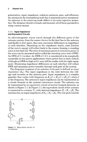
is the frequency. The antenna’s input impedance can be represented as
a circuit element in the system’s microwave circuit. The antenna can
be represented by an equivalent circuit of several lumped elements, as
shown in Figure 1.1. In Figure 1.1, the equivalent circuit of the antenna
, with internal impedance, Z = R + jX . The
is connected to a source, V s s s s
antenna has an input impedance of Z = R a + jX a . The real part consists
in
X s R r
R s
R l
V s
X a
Z in
Figure 1.1 Equivalent circuit of
an antenna