
Page 31 - Antennas for Base Stations in Wireless Communications
P. 31
4 Chapter One
The bandwidth is the antenna operating frequency band within which
the antenna performs as desired. The bandwidth could be related to the
antenna matching band if its radiation patterns do not change within
this band. In fact, this is the case for small antennas where a fundamen-
tal limit relates bandwidth, size, and efficiency. The bandwidth of other
antennas might be affected by the radiation pattern’s characteristics,
and the radiation characteristics might change although the matching
of the antenna is acceptable. We can define antenna bandwidth in sev-
eral ways. Ratio bandwidth (BW r ) is
f
BW = f U L (1.5)
r
where f U and f L are the upper and lower frequency of the band, respec-
tively. The other definition is the percentage bandwidth (WB p ) and is
related to the ratio bandwidth as
f − f WB −1
BW = 200 U L % = 200 r % (1.6)
f +
p
U f L WB +1
r
1.1.3 Radiation Patterns
Radiation patterns are graphical representations of the electromagnetic
power distribution in free space. Also, these patterns can be considered
to be representative of the relative field strengths of the field radiated
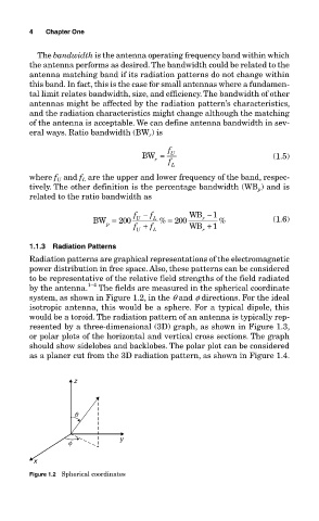
by the antenna. 1–4 The fields are measured in the spherical coordinate
system, as shown in Figure 1.2, in the q and f directions. For the ideal
isotropic antenna, this would be a sphere. For a typical dipole, this
would be a toroid. The radiation pattern of an antenna is typically rep-
resented by a three-dimensional (3D) graph, as shown in Figure 1.3,
or polar plots of the horizontal and vertical cross sections. The graph
should show sidelobes and backlobes. The polar plot can be considered
as a planer cut from the 3D radiation pattern, as shown in Figure 1.4.
z
q
f y
x
Figure 1.2 Spherical coordinates