Page 32 - Antennas for Base Stations in Wireless Communications
P. 32

Fundamentals of Antennas        5

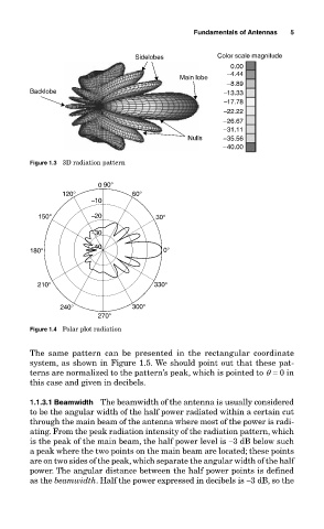
                                            Sidelobes           Color scale magnitude
                                                                    0.00
                                                                   -4.44
                                                       Main lobe
                                                                   -8.89
                  Backlobe                                        -13.33
                                                                  -17.78
                                                                  -22.22
                                                                  -26.67
                                                                  -31.11
                                                         Nulls    -35.56
                                                                  -40.00
                  Figure 1.3  3D radiation pattern


                                   0  90°
                          120°             60°
                                 -10
                    150°         -20             30°

                                 -30
                                 -40
                  180°                             0°


                    210°                         330°

                          240°             300°
                                   270°
                  Figure 1.4  Polar plot radiation

                  The  same  pattern  can  be  presented  in  the  rectangular  coordinate
                  system, as shown in Figure 1.5. We should point out that these pat-
                  terns are normalized to the pattern’s peak, which is pointed to q  = 0 in
                  this case and given in decibels.

                  1.1.3.1 Beamwidth  The beamwidth of the antenna is usually considered
                  to be the angular width of the half power radiated within a certain cut
                  through the main beam of the antenna where most of the power is radi-
                  ating. From the peak radiation intensity of the radiation pattern, which
                  is the peak of the main beam, the half power level is −3 dB below such
                  a peak where the two points on the main beam are located; these points
                  are on two sides of the peak, which separate the angular width of the half
                  power. The angular distance between the half power points is defined
                  as the beamwidth. Half the power expressed in decibels is −3 dB, so the
   27   28   29   30   31   32   33   34   35   36   37