
Page 291 - Antennas for Base Stations in Wireless Communications
P. 291
264 Chapter Seven
H-plane, Co-pol E-plane, Co-pol
H-plane, Cross-pol E-plane, Cross-pol
0
15
−5 10
−10 5
|S 11 |, dB −15 Gain, dBi 0
−20 −5
−10
−25
−15
−30
2 3 4 5 6 7 8 9 10 4.8 5.0 5.2 5.4 5.6 5.8 6.0
Frequency, GHz Frequency, GHz
(d) (e)
H-plane, Ant. 0 E-plane, Ant. 0
f 4.9 GHz Co-pol f 4.9 GHz Co-pol
f 4.9 GHz Cross-pol f 4.9 GHz Cross-pol
q = 0° q = 0°
f 5.5 GHz Co-pol f 5.5 GHz Co-pol
f 5.5 GHz Cross-pol f 5.5 GHz Cross-pol
f 5.9 GHz Co-pol f 5.9 GHz Co-pol
f 5.9 GHz Cross-pol f 5.9 GHz Cross-pol
−90° 90° −90° 90°
0 0
10 10
15 (dBi) 15 (dBi) f 4.9 GHz Co-pol
180° 180°
(f) (g)
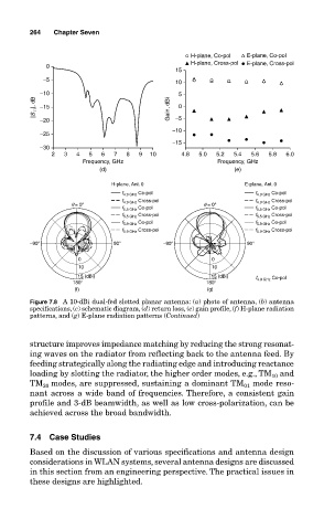
Figure 7.8 A 10-dBi dual-fed slotted planar antenna: (a) photo of antenna, (b) antenna
specifications, (c) schematic diagram, (d) return loss, (e) gain profile, (f) H-plane radiation
patterns, and (g) E-plane radiation patterns (Continued)
structure improves impedance matching by reducing the strong resonat-
ing waves on the radiator from reflecting back to the antenna feed. By
feeding strategically along the radiating edge and introducing reactance
loading by slotting the radiator, the higher order modes, e.g., TM 10 and
TM 20 modes, are suppressed, sustaining a dominant TM 01 mode reso-
nant across a wide band of frequencies. Therefore, a consistent gain
profile and 3-dB beamwidth, as well as low cross-polarization, can be
achieved across the broad bandwidth.
7.4 Case Studies
Based on the discussion of various specifications and antenna design
considerations in WLAN systems, several antenna designs are discussed
in this section from an engineering perspective. The practical issues in
these designs are highlighted.