
Page 293 - Antennas for Base Stations in Wireless Communications
P. 293
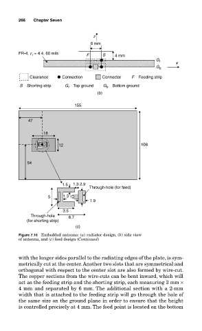
266     Chapter Seven

                                                z
                                               6 mm
                  FR-4, e  = 4.4, 60 mils    F     S    4 mm
                        r
                                                                        G t
                                                                                x
                                                                        G b
                       Clearance    Connection     Connector   F    Feeding strip
                   S    Shorting strip  G     Top ground  G     Bottom ground
                                                     b
                                      t
                                                 (b)
                                        155


                      47

                            18

                                  12                               108


                      54


                                    1.5  1.3  2.9
                                              Through-hole (for feed)
                              5     1.3 1
                                              1.9

                                    3.5
                       Through-hole   6.7
                      (for shorting strip)
                                         (c)
                  Figure 7.10  Embedded antenna: (a) radiator design, (b) side view
                  of antenna, and (c) feed design (Continued)


                  with the longer sides parallel to the radiating edges of the plate, is sym-
                  metrically cut at the center. Another two slots that are symmetrical and
                  orthogonal with respect to the center slot are also formed by wire-cut.
                  The copper sections from the wire-cuts can be bent inward, which will
                  act as the feeding strip and the shorting strip, each measuring 3 mm ×
                  4 mm and separated by 6 mm. The additional section with a 2-mm
                  width that is attached to the feeding strip will go through the hole of
                  the same size on the ground plane in order to ensure that the height
                  is controlled precisely at 4 mm. The feed point is located on the bottom