Page 292 - Antennas for Base Stations in Wireless Communications
P. 292

Antennas for WLAN (WiFi) Applications        265

                  7.4.1  Indoor P2MP
                  Embedded Antenna
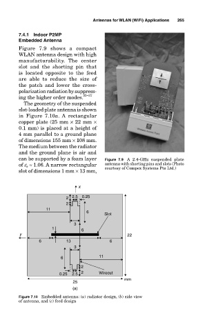
                  Figure  7.9  shows  a  compact
                  WLAN antenna design with high
                  manufacturability.  The  center
                  slot  and  the  shorting  pin  that
                  is  located  opposite  to  the  feed
                  are  able  to  reduce  the  size  of
                  the  patch  and  lower  the  cross-
                  polarization radiation by suppress-
                  ing the higher order modes. 35−37
                    The geometry of the suspended
                  slot-loaded plate antenna is shown
                  in  Figure  7.10a.  A  rectangular
                  copper plate (25 mm × 22 mm ×
                  0.1 mm) is placed at a height of
                  4 mm parallel to a ground plane
                  of dimensions 155 mm × 108 mm.
                  The medium between the radiator
                  and the ground plane is air and
                  can be supported by a foam layer   Figure  7.9  A  2.4-GHz  suspended  plate
                  of e r  ≈ 1.06. A narrow rectangular   antenna with shorting pins and slots (Photo
                  slot of dimensions 1 mm × 13 mm,   courtesy of Compex Systems Pte Ltd.)


                                          x

                                     2  2.5  0.25
                                     2
                             11
                                             6      Slot

                                        3
                               1           6
                   y                                         22
                          6          13               6
                                        3
                                   6              11
                                           2
                                  0.25  2.5  2    Wirecut
                                                            mm
                                        25
                                        (a)
                  Figure 7.10  Embedded antenna: (a) radiator design, (b) side view
                  of antenna, and (c) feed design
   287   288   289   290   291   292   293   294   295   296   297