
Page 91 - Antennas for Base Stations in Wireless Communications
P. 91
64 Chapter Two
A significant problem encountered with laterally combined arrays is
that each array operates in an unsymmetrical environment: the reflec-
tor extends farther on one side of each element column than it does
on the other, so the azimuth pattern is unsymmetrical and the beam
maximum may squint off-axis. The second array suffers a mirror-image
squint, so there may be a substantial difference between the boresight
direction of the two beams even when the array design is identical for
both element columns. A degree of compensation can be obtained if some
16
elements of each array are transposed between columns; although if
complete symmetry is to be obtained, the azimuth beamwidth will be
reduced. Techniques of this kind must be applied with care because
the elevation patterns of a non-collinear array differ as a function of
azimuth direction.
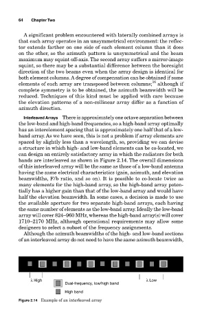
Interleaved Arrays There is approximately one octave separation between
the low-band and high-band frequencies, so a high-band array optimally
has an interelement spacing that is approximately one half that of a low-
band array. As we have seen, this is not a problem if array elements are
spaced by slightly less than a wavelength, so, providing we can devise
a structure in which high- and low-band elements can be co-located, we
can design an entirely satisfactory array in which the radiators for both
bands are interleaved as shown in Figure 2.14. The overall dimensions
of this interleaved array will be the same as those of a low-band antenna
having the same electrical characteristics (gain, azimuth, and elevation
beamwidths, F/b ratio, and so on). It is possible to co-locate twice as
many elements for the high-band array, so the high-band array poten-
tially has a higher gain than that of the low-band array and would have
half the elevation beamwidth. In some cases, a decision is made to use
the available aperture for two separate high-band arrays, each having
the same number of elements as the low-band array. Ideally the low-band
array will cover 824–960 MHz, whereas the high-band array(s) will cover
1710–2170 MHz, although operational requirements may allow some
designers to select a subset of the frequency assignments.
Although the azimuth beamwidths of the high- and low-band sections
of an interleaved array do not need to have the same azimuth beamwidth,
λ High λ Low
Dual-frequency, low/high band
High band
Figure 2.14 Example of an interleaved array