
Page 87 - Antennas for Base Stations in Wireless Communications
P. 87
60 Chapter Two
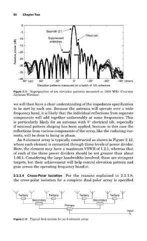
0
−5 Beamtilt (2°)
Filled null
−10 Suppressed
Relative power (dB) −15
sidelobes
−20
−25
−30
−35
−40
90° (up) 60° 30° 0° −30° −60° −90° (down)
Elevation patterns measured on a batch of 12λ antennas
Figure 2.11 Superposition of ten elevation patterns measured at 1800 MHz (Courtesy
Jaybeam Wireless)
we will then have a clear understanding of the impedance specification
to be met by each one. Because the antenna will operate over a wide
frequency band, it is likely that the individual reflections from separate
components will add together unfavorably at some frequencies. This
is particularly likely for an antenna with 0° electrical tilt, especially
if minimal pattern shaping has been applied, because in this case the
reflections from various components of the array, like the radiating cur-
rents, will be close to being in phase.
An 8-element array is typically constructed as shown in Figure 2.12,
where each element is connected through three levels of power divider.
Here, the element may have a maximum VSWR of 1.2:1, whereas that
of each of the three power dividers should be not greater than about
1.06:1. Considering the large bandwidths involved, these are stringent
targets, but their achievement will help control elevation pattern and
gain across the operating frequency band(s).
2.3.3.4 Cross-Polar Isolation For the reasons explained in 2.2.1.8,
the cross-polar isolation for a complete dual-polar array is specified
Tertiary Tertiary Tertiary Tertiary
Secondary Secondary
Primary
Input
Figure 2.12 Typical feed system for an 8-element array