
Page 88 - Antennas for Base Stations in Wireless Communications
P. 88
Base Station Antennas for Mobile Radio Systems 61
as >30 dB. The target isolation for an individual tier should be at least
this, or perhaps >33 dB, but even if perfect isolation is obtained for a
single tier, the mutual impedances between tiers will generally reduce
this to around 26 dB, especially for small values of beamtilt. The required
isolation can be restored by introducing some intentional compensating
coupling. When considering the XPI of a single element pair, coupling may
occur because of lack of symmetry in the element or in its environment
in the array. A dipole square configuration (Figure 2.6) is symmetrical if
the individual dipoles are driven through effective baluns, but a crossed
dipole always has some degree of asymmetry caused by the feed method at
its center. A square or circular patch or stacked patch is asymmetric unless
two balanced feed points are provided in each polarization plane.
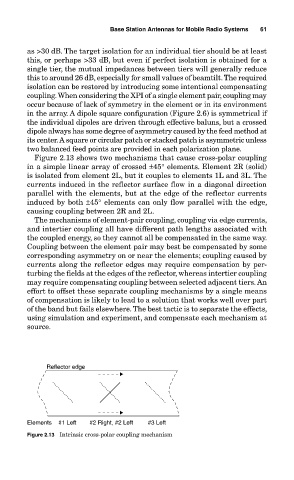
Figure 2.13 shows two mechanisms that cause cross-polar coupling
in a simple linear array of crossed ±45° elements. Element 2R (solid)
is isolated from element 2L, but it couples to elements 1L and 3L. The
currents induced in the reflector surface flow in a diagonal direction
parallel with the elements, but at the edge of the reflector currents
induced by both ±45° elements can only flow parallel with the edge,
causing coupling between 2R and 2L.
The mechanisms of element-pair coupling, coupling via edge currents,
and intertier coupling all have different path lengths associated with
the coupled energy, so they cannot all be compensated in the same way.
Coupling between the element pair may best be compensated by some
corresponding asymmetry on or near the elements; coupling caused by
currents along the reflector edges may require compensation by per-
turbing the fields at the edges of the reflector, whereas intertier coupling
may require compensating coupling between selected adjacent tiers. An
effort to offset these separate coupling mechanisms by a single means
of compensation is likely to lead to a solution that works well over part
of the band but fails elsewhere. The best tactic is to separate the effects,
using simulation and experiment, and compensate each mechanism at
source.
Reflector edge
Elements #1 Left #2 Right, #2 Left #3 Left
Figure 2.13 Intrinsic cross-polar coupling mechanism