
Page 85 - Antennas for Base Stations in Wireless Communications
P. 85
58 Chapter Two
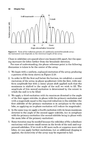
3-dB beamwidth
13.6dB
Relative power (dB)
Up 0° Down
Angle above/below horizontal
Figure 2.10 Form of the radiation pattern of a uniformly excited broadside array;
the horizontal scale depends on the electrical length of the array.
Close-in sidelobes are spaced about one beamwidth apart, but the spac-
ing increases for lobes farther from the broadside direction.
For ease of understanding, the phase reference point in the following
discussion is taken to be the center of the array.
1. We begin with a uniform, cophased excitation of the array, producing
a pattern of the form shown in Figure 2.10.
2. In order to fill the first null below the horizon, we establish a second
excitation of the array, in phase quadrature with the first, with uni-
form amplitude but with a linear phase shift applied such that the
maximum is shifted to the angle of the null we wish to fill. The
amplitude of this second excitation is determined by the extent to
which the null is to be filled.
3. We apply a third excitation with its maximum directed to the angle
of the first upper sidelobe, in phase with the primary excitation and
with a magnitude equal to the required reduction in the sidelobe (the
first sidelobe of the primary excitation is in antiphase to the main
lobe, so applying an in-phase excitation will reduce its magnitude).
4. In the same way, we apply a fourth excitation with its beam maximum
directed to the angle of the second upper sidelobe, but in antiphase
with the primary excitation (the second sidelobe being in phase with
the main lobe of the primary excitation).
5. Some iteration may be needed because the sidelobes of the subsidiary
excitations will create small errors in the levels of the null and sup-
pressed sidelobes. If we wish to fill more nulls or suppress more side
lobes, we can apply further excitations, but as additional shaping is
applied, the directivity of the array may be expected to fall.