
Page 80 - Antennas for Base Stations in Wireless Communications
P. 80
Base Station Antennas for Mobile Radio Systems 53
downward, the upper grating lobe will grow in amplitude and the loss
of directivity caused by overspacing will increase. We must, therefore,
choose the element spacing after computing the directivity/frequency
relationship with the maximum required electrical tilt applied. The rate
at which the grating lobes grow as the spacing exceeds 1l depends on
the elevation pattern of the individual elements—those with significant
radiation close to the array axis must be spaced closer than elements
with low radiation in this direction.
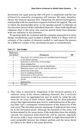
To optimize both the technical and the economic parameters of array
design, establishing a gain budget is helpful (Table 2.2). Begin with an
estimate of the number of elements needed (n) and repeat the process
for a different number if the calculated net gain is unsatisfactory.
TABLE 2.2 Gain Budget
Reference
(see below) Parameter dB
a Directivity of a uniform array of n omnidirectional elements
at the chosen spacing
b Reduction in directivity at band edges
c Beam shaping loss
d Allowance for imperfect current distribution
e Max/mean power ratio of the azimuth pattern
f Directivity of the array
g Loss in radiating elements
h Attenuation in feed network
i Attenuation of cable from connector to primary power
divider
j Radome loss
k Net gain
a. This value is obtained by integration of the elevation pattern of a
collinear array of the chosen radiating elements. For a vertically
polarized array an approximation may be made by using the pat-
terns for an array of short vertical dipoles, but for slant-polarized
arrays this approximation may lead to underestimation of the grat-
ing lobes and a consequent overestimation of the directivity of the
real array. The elevation pattern maximum of individual tiers must
lie in the horizontal plane. Although the beamtilt of the array will
be determined by the array factor, if the individual tiers fire slightly
upward, the maximum total directivity will be reduced, especially
for arrays with a large electrical downtilt. A slight downward tilt is
more acceptable because the element pattern and the array factor
are likely to be tilted in the same direction.