
Page 79 - Antennas for Base Stations in Wireless Communications
P. 79
52 Chapter Two
d/k
n 1 ⁄ 4 3 ⁄ 8 1 ⁄ 2 5 ⁄ 8 3 ⁄ 4 7 ⁄ 8 1
4 2.45 3.39 4.29 5.21 6.05 6.84 6.95
5 2.94 4.05 5.30 6.45 7.55 8.59 8.86
6 3.44 4.87 6.29 7.81 9.15 10.37 10.77
14
13
12
11
n = 16
10
9
Normalized D s , dB 8 12
8
7
6
5
4 6
4
3
3
2
2
1
0
0 0.1 0.2 0.3 0.4 0.5 0.6 0.7 0.8 0.9 1.0 1.1 1.2
d/λ
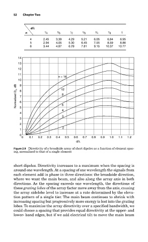
Figure 2.9 Directivity of a broadside array of short dipoles as a function of element spac-
ing, normalized to that of a single element
short dipoles. Directivity increases to a maximum when the spacing is
around one wavelength. At a spacing of one wavelength the signals from
each element add in phase in three directions: the broadside direction,
where we want the main beam, and also along the array axis in both
directions. As the spacing exceeds one wavelength, the directions of
these grating lobes of the array factor move away from the axis, causing
the array sidelobe level to increase at a rate determined by the eleva-
tion pattern of a single tier. The main beam continues to shrink with
increasing spacing but progressively more energy is lost into the grating
lobes. To maximize the array directivity over a specified bandwidth, we
could choose a spacing that provides equal directivity at the upper- and
lower- band edges, but if we add electrical tilt to move the main beam