
Page 74 - Antennas for Base Stations in Wireless Communications
P. 74
Base Station Antennas for Mobile Radio Systems 47
(a)
(c)
(b)
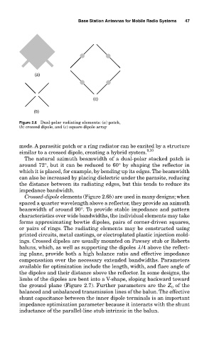
Figure 2.6 Dual-polar radiating elements: (a) patch,
(b) crossed dipole, and (c) square dipole array
mode. A parasitic patch or a ring radiator can be excited by a structure
similar to a crossed dipole, creating a hybrid system. 9,10
The natural azimuth beamwidth of a dual-polar stacked patch is
around 72°, but it can be reduced to 60° by shaping the reflector in
which it is placed, for example, by bending up its edges. The beamwidth
can also be increased by placing dielectric under the parasite, reducing
the distance between its radiating edges, but this tends to reduce its
impedance bandwidth.
Crossed-dipole elements (Figure 2.6b) are used in many designs; when
spaced a quarter wavelength above a reflector, they provide an azimuth
beamwidth of around 90°. To provide stable impedance and pattern
characteristics over wide bandwidths, the individual elements may take
forms approximating bowtie dipoles, pairs of corner-driven squares,
or pairs of rings. The radiating elements may be constructed using
printed circuits, metal castings, or electroplated plastic injection mold-
ings. Crossed dipoles are usually mounted on Pawsey stub or Roberts
baluns, which, as well as supporting the dipoles l /4 above the reflect-
ing plane, provide both a high balance ratio and effective impedance
compensation over the necessary extended bandwidths. Parameters
available for optimization include the length, width, and flare angle of
the dipoles and their distance above the reflector. In some designs, the
limbs of the dipoles are bent into a V-shape, sloping backward toward
the ground plane (Figure 2.7). Further parameters are the Z 0 of the
balanced and unbalanced transmission lines of the balun. The effective
shunt capacitance between the inner dipole terminals is an important
impedance optimization parameter because it interacts with the shunt
inductance of the parallel-line stub intrinsic in the balun.