
Page 69 - Antennas for Base Stations in Wireless Communications
P. 69
42 Chapter Two
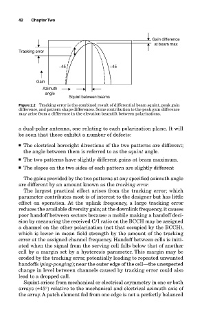
Gain difference
at beam max
Tracking error
−45 +45
Gain
Azimuth
angle
Squint between beams
Figure 2.2 Tracking error is the combined result of differential beam squint, peak gain
difference, and pattern shape differences. Some contribution to the peak gain difference
may arise from a difference in the elevation beamtilt between polarizations.
a dual-polar antenna, one relating to each polarization plane. It will
be seen that these exhibit a number of defects:
■ The electrical boresight directions of the two patterns are different;
the angle between them is referred to as the squint angle.
■ The two patterns have slightly different gains at beam maximum.
■ The slopes on the two sides of each pattern are slightly different
The gains provided by the two patterns at any specified azimuth angle
are different by an amount known as the tracking error.
The largest practical effect arises from the tracking error; which
parameter contributes most is of interest to the designer but has little
effect on operation. At the uplink frequency, a large tracking error
reduces the available diversity gain; at the downlink frequency, it causes
poor handoff between sectors because a mobile making a handoff deci-
sion by measuring the received C/I ratio on the BCCH may be assigned
a channel on the other polarization (not that occupied by the BCCH),
which is lower in mean field strength by the amount of the tracking
error at the assigned channel frequency. Handoff between cells is initi-
ated when the signal from the serving cell falls below that of another
cell by a margin set by a hysteresis parameter. This margin may be
eroded by the tracking error, potentially leading to repeated unwanted
handoffs (ping-ponging); near the outer edge of the cell—the unexpected
change in level between channels caused by tracking error could also
lead to a dropped call.
Squint arises from mechanical or electrical asymmetry in one or both
arrays (±45°) relative to the mechanical and electrical azimuth axis of
the array. A patch element fed from one edge is not a perfectly balanced