
Page 72 - Antennas for Base Stations in Wireless Communications
P. 72
Base Station Antennas for Mobile Radio Systems 45
a brief summary of possible classes of design. Radiating element design
has responded to the increasing demand for operation over ever wider
bandwidths, but in addition to meeting a stringent electrical specifica-
tion, a successful design must also be capable of low-cost, high-volume
production with consistent electrical performance.
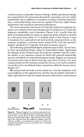
The most commonly used forms of vertically polarized radiating ele-
ments are variants of the basic designs shown in Figure 2.3. To provide
adequate bandwidth, patch elements (Figure 2.4a) usually take the
form of stacked patches in which an upper parasitic radiator is excited
6
by a fed patch lying below it. A stacked patch of this format is easy
to integrate into a printed-circuit feed network (corporate feed), so the
antenna comprises a printed circuit board (PCB) with the parasitic
patches attached to it, typically with push-in plastic spacers.
The reflecting plane behind dipole elements may be flat, curved, bent,
or have up-standing flanges along its longitudinal edges. Optimizing
the spacing of the element from the reflector, together with the reflec-
tor profile, is an important means by which the azimuth beamwidth
may be controlled over extended frequency bands. Dipoles are balanced
structures and must be driven through some form of balun, the most
common forms for BS antennas being the Pawsey stub and its printed-
circuit derivative the Roberts balun, sometimes called the hairpin balun
(Figure 2.4).
Microstrip feed networks can be etched on a low-loss laminate with
a groundplane on the opposite face, but the cost of suitable materials is
high, especially for large low-band antennas. Alternative constructions
Figure 2.3 Typical designs for a vertically polarized radi-
ating element. The reflecting plane behind the elements
may be flat, curved, bent, or have up-standing flanges
along its longitudinal edges. Optimization of the spac-
ing of the element from the reflector, together with the
reflector profile, is an important means by which the
azimuth beamwidth may be controlled over extended
frequency bands.