
Page 73 - Antennas for Base Stations in Wireless Communications
P. 73
46 Chapter Two
(a) (b)
Figure 2.4 Pawsey stub (a) and Roberts (hairpin) balun (b)
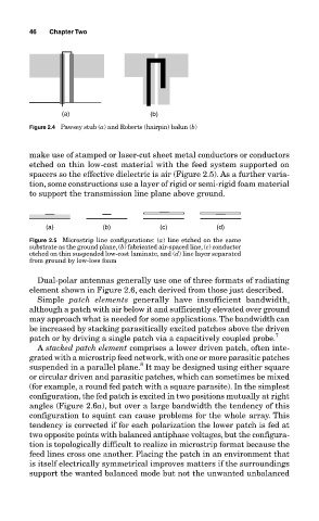
make use of stamped or laser-cut sheet metal conductors or conductors
etched on thin low-cost material with the feed system supported on
spacers so the effective dielectric is air (Figure 2.5). As a further varia-
tion, some constructions use a layer of rigid or semi-rigid foam material
to support the transmission line plane above ground.
(a) (b) (c) (d)
Figure 2.5 Microstrip line configurations: (a) line etched on the same
substrate as the ground plane, (b) fabricated air-spaced line, (c) conductor
etched on thin suspended low-cost laminate, and (d) line layer separated
from ground by low-loss foam
Dual-polar antennas generally use one of three formats of radiating
element shown in Figure 2.6, each derived from those just described.
Simple patch elements generally have insufficient bandwidth,
although a patch with air below it and sufficiently elevated over ground
may approach what is needed for some applications. The bandwidth can
be increased by stacking parasitically excited patches above the driven
patch or by driving a single patch via a capacitively coupled probe. 7
A stacked patch element comprises a lower driven patch, often inte-
grated with a microstrip feed network, with one or more parasitic patches
8
suspended in a parallel plane. It may be designed using either square
or circular driven and parasitic patches, which can sometimes be mixed
(for example, a round fed patch with a square parasite). In the simplest
configuration, the fed patch is excited in two positions mutually at right
angles (Figure 2.6a), but over a large bandwidth the tendency of this
configuration to squint can cause problems for the whole array. This
tendency is corrected if for each polarization the lower patch is fed at
two opposite points with balanced antiphase voltages, but the configura-
tion is topologically difficult to realize in microstrip format because the
feed lines cross one another. Placing the patch in an environment that
is itself electrically symmetrical improves matters if the surroundings
support the wanted balanced mode but not the unwanted unbalanced